


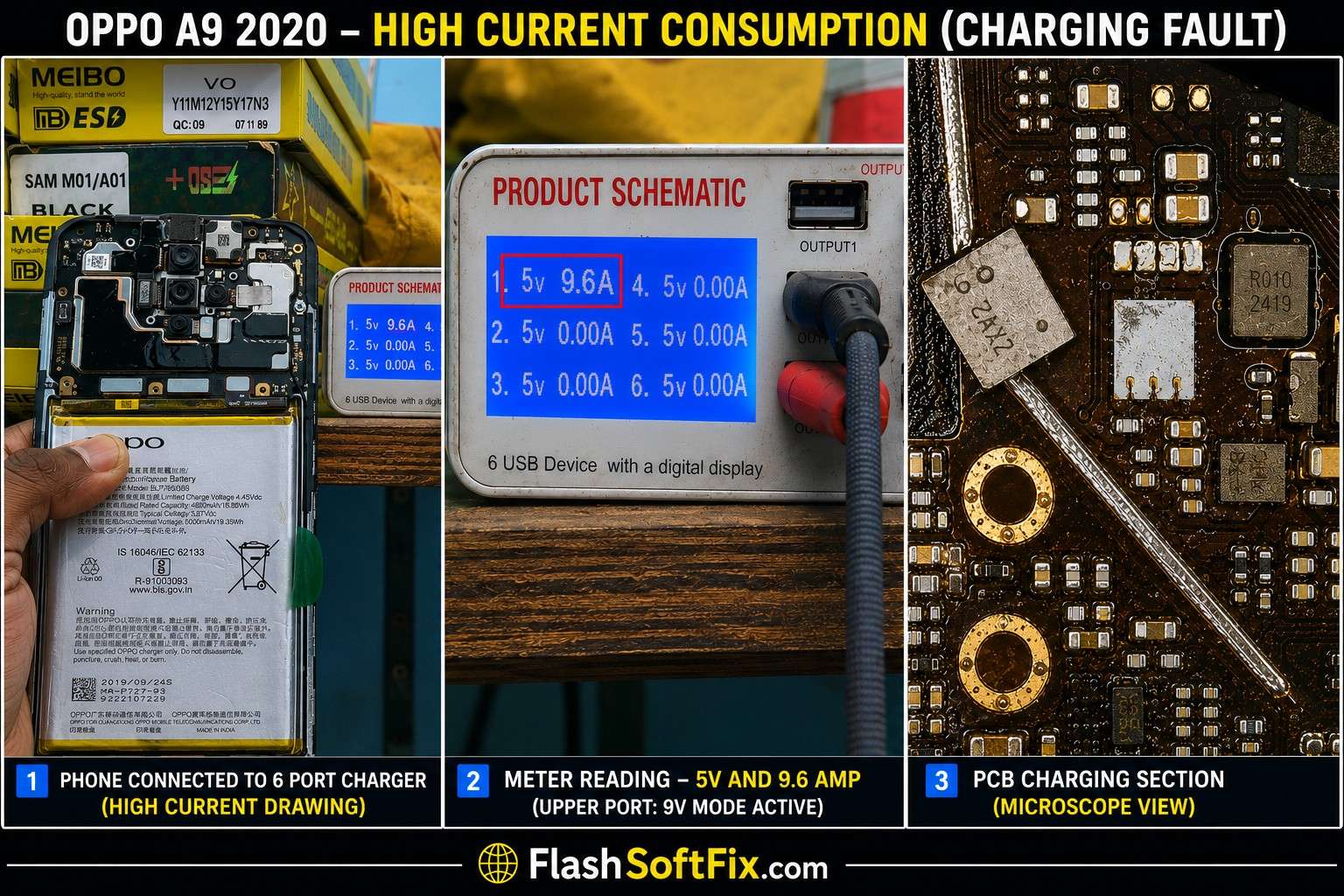
A customer recently brought an OPPO A9 2020 to our mobile repair shop with a charging problem.
At first, the fault looked like it could be related to the charging sub-board, B2B connection or charging port. However, replacing the related parts did not solve the problem.
The actual fault was eventually found on the VCHARG line, which was shorted by a protection component.
Using a Borneo Schematic diagram, a controlled 5V injection and a thermal camera, we were able to locate the faulty component. After removing the shorted protection diode, the phone started charging normally.
This article documents the complete diagnosis and repair process.
OPPO A9 2020 Charging Problem
Device
OPPO A9 2020
Customer Complaint
The customer’s main complaint was:
Phone is not charging.
The first step was to determine what was happening when a charger was connected.
Initial Test With a 6-Port Charger
We connected the OPPO A9 2020 to our 6-port USB charger/tester to observe its current behavior.
The result was unusual.
The device was taking approximately:
9.6A
The current was extremely high for a phone charging test.
At times, the high-current condition was severe enough that the display on the 6-port charger/tester went black.
This immediately indicated that we were not dealing with a normal “slow charging” or simple charging-port problem.
There was a strong indication of a short circuit somewhere in the charging/power path.
First Attempt – Check the B2B Connection and Sub-Board
Before moving directly to motherboard-level troubleshooting, we checked the components associated with the charging path.
We tried:
- Checking the B2B connection
- Replacing the B2B flex
- Replacing the charging sub-board
However, the problem remained.
The phone still showed the same abnormal high-current behavior.
This was an important diagnostic result.
The sub-board and B2B flex were therefore less likely to be the root cause.
We needed to investigate the motherboard.
Moving to Motherboard-Level Diagnosis
At this point, we started checking the motherboard using a Borneo Schematic diagram.
A schematic is extremely useful during this type of repair because it allows us to identify individual power rails and understand where a particular charging voltage travels through the board.
Instead of replacing components randomly, we could now follow the charging circuit and check the relevant lines.
During the measurements, we found an important fault.

VCHARG Line Found Shorted
While checking the B2B connector values and related charging lines according to the schematic, we found that the:
VCHARG line was short-circuited.
This was a major breakthrough.
The VCHARG line is part of the charging power path, so a short on this line can result in an abnormal current draw when a charger or power source is connected.
The next challenge was finding exactly which component was causing the short.
Using 5V Injection to Locate the Short
To locate the faulty component, we used a controlled voltage injection technique.
We applied:
5V to the VCHARG line
The purpose of voltage injection was not to randomly power the board, but to locate the component responsible for the short.
When voltage is injected into a shorted power rail, the faulty component can sometimes become warmer than the surrounding components.
That temperature difference can then be detected using a thermal imaging camera.
Thermal Camera Helps Locate the Fault
We monitored the motherboard using a thermal camera while the 5V injection was applied.
The thermal image immediately gave us a useful clue.
One component started heating up significantly.
After tracing its position on the circuit, we identified the component as part of the protection circuit on the VCHARG line.
This type of protection component is designed to help protect the circuit from abnormal electrical conditions.
However, in this case, the component itself had become the source of the short.
Faulty Protection Diode Identified
The component that was heating up was a protection diode connected to the charging-related circuit.
Because it was responsible for the VCHARG line short, it had to be removed.
We carefully removed the faulty protection diode from the motherboard.
After removing the component, we checked the VCHARG line again.
The short was no longer present.
This confirmed that we had located the source of the problem.
Charging Test After Removing the Diode
After removing the shorted protection component, we reassembled the required connections and tested the phone again.
We connected the charger and monitored the charging behavior.
This time, the previous abnormal high-current condition was gone.
The OPPO A9 2020 started charging normally.
The charging function was restored successfully.
Complete Diagnostic Process
The repair can be summarized as follows:
Customer complaint
↓
OPPO A9 2020 not charging
↓
Connected to 6-port charger/tester
↓
Approximately 9.6A abnormal current
↓
Tester screen sometimes went black
↓
Checked/replaced B2B flex
↓
Replaced charging sub-board
↓
Problem remained
↓
Checked motherboard using Borneo Schematic
↓
VCHARG line found shorted
↓
Injected 5V into VCHARG line
↓
Thermal camera used to locate heating component
↓
Protection diode identified
↓
Faulty diode removed
↓
VCHARG short cleared
↓
Charging restored successfully
Why We Used a Thermal Camera
A thermal camera can be extremely useful when diagnosing short circuits on mobile phone motherboards.
A multimeter can tell us that a power line is shorted, but it may not immediately tell us which component is responsible for the short.
With controlled voltage injection, the shorted component may dissipate power and become warmer than the surrounding components.
The thermal camera makes that temperature difference visible.
In this OPPO A9 2020 repair, the thermal camera helped us quickly identify the component that was heating on the VCHARG line.
Why Replacing the Sub-Board Did Not Fix the Problem
Many modern smartphones have separate charging sub-boards connected to the main motherboard through a B2B flex.
When a phone does not charge, it is reasonable to inspect:
- Charging port
- Charging sub-board
- B2B flex
- B2B connectors
- Charging-related lines
However, not every charging problem originates from the sub-board.
In this case, even after checking/replacing the B2B flex and sub-board, the phone continued to draw abnormally high current.
The actual problem was on the motherboard VCHARG line.
This is why systematic diagnosis is important before replacing parts.
The Importance of Schematic-Based Diagnosis
The Borneo Schematic diagram was particularly useful in this repair.
Instead of guessing which components were connected to the charging circuit, we could identify the VCHARG line and check its condition at the B2B connector.
Once the VCHARG line was confirmed to be shorted, the troubleshooting direction became much clearer.
This approach can save considerable time compared with replacing charging components one by one.
Final Repair Result
After removing the faulty protection diode:
- VCHARG short was cleared
- Abnormal current draw was eliminated
- Charging operation was restored
- The phone charged normally
Final diagnosis:
OPPO A9 2020 – Not Charging
Fault: VCHARG line short
Cause: Shorted protection diode
Diagnosis tools: Borneo Schematic + thermal camera
Fault-finding method: 5V voltage injection
Repair: Removed faulty protection diode
Result: Charging working normally
Important Safety Note About Voltage Injection
Voltage injection is a professional motherboard troubleshooting technique and should be performed carefully.
The injection voltage and current limit should be appropriate for the specific circuit being tested.
Before injecting voltage into any rail:
- Identify the correct line from the schematic.
- Confirm the rail’s expected voltage.
- Use a suitable laboratory power supply.
- Set an appropriate current limit.
- Avoid excessive voltage.
- Monitor the board carefully.
- Use thermal imaging or another suitable method to locate heating components.
- Understand the circuit before removing protection components.
A protection component may have an important role in protecting the phone from overvoltage, ESD or other abnormal electrical conditions. Removing such a component should therefore be treated as a repair decision based on proper diagnosis, not as a universal solution.
Conclusion
This OPPO A9 2020 repair is a good example of why a not-charging problem should not always be diagnosed by simply replacing the charging sub-board or charging port.
The phone initially showed an extremely high current reading of approximately 9.6A on our 6-port charger/tester, and the tester’s screen would sometimes go black because of the abnormal condition.
After checking the B2B flex and replacing the charging sub-board without success, we moved to motherboard-level diagnosis.
Using the Borneo Schematic diagram, we checked the charging-related lines and discovered that the VCHARG line was shorted.
We then applied a controlled 5V injection to the affected line and used a thermal camera to locate the component that was heating.
The faulty component was a protection diode in the charging circuit.
After removing the diode, the VCHARG short was cleared and the OPPO A9 2020 began charging normally again.
The main lesson from this repair:
When a phone shows extremely high current during charging, don’t immediately replace the charging sub-board. Check the relevant power rails, use the schematic to locate the short, and use controlled voltage injection with thermal imaging to find the faulty component.
This systematic approach can turn a difficult charging fault into a successful motherboard-level repair.

